
107 Scintillator
An analog-computer-style test-gear card. Two audio inputs feed an 8-way "argument" stage (add, subtract, multiply, ratio, magnitude...) and then a 6-way classic analog-computer "function" stage (log, root, square, differentiator), blended dry-to-wet on Audio Out 1. Audio Out 2 is a synthesised kick drum triggered from Pulse In 1 - deliberately independent of the rest of the card so it holds a steady rhythm underneath - tuned by the MAIN knob, with CV In 1 and CV In 2 shaping its attack and decay and a tap of the switch cycling three envelope presets. Two pulse outputs behave like Geiger-counter gates, firing stochastically when the two inputs "collide", with the collision's "violence" setting both the odds of firing and the pulse width. Switch Up swaps Knob X/Y/MAIN into a simple 2-input mixer with a dry/wet blend.
Panel
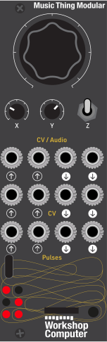 Kick PitchArgument SelectFunction SelectABKick AttackKick DecayKick TriggerMain OutKick OutGate 1 (A-led collision)Gate 2 (B-led collision)
Controls
Kick Pitch
DSP mode: tunes the kick drum across roughly 35-160Hz, exponentially so the knob is even across its travel. The preset shifts that range - short and snappy sits a quarter higher, deep and low a quarter lower. Pot-pickup guarded, so it holds its value across a trip to the up position and only resumes tracking once MAIN returns to it.
Argument Select
DSP mode: 8-way select (with hysteresis at each boundary) - A / B / A+B / A-B / A*B/10 / sqrt(A^2+B^2) / A/|B| / 10*A/|B|. Mix mode: Audio In 1 level.
Function Select
DSP mode: 6-way select (with hysteresis at each boundary) - ln(|x|+1) / sqrt(|x|) / x (none) / x^2 / -dx/dt /100 / -dx/dt, applied to the argument stage's output. Mix mode: Audio In 2 level.
Mix Mode: Knob X and Y become Audio In 1/2 level controls (0 = silence, fully CW = unity), and Knob MAIN becomes a dry/wet blend on Audio Out 1. All three knobs use pot pickup, so each job keeps the value it was left at when the switch moves and only resumes tracking once the knob returns to it - nothing jumps in either direction.
DSP Mode: Knob X selects one of 8 argument operations on A/B, Knob Y selects one of 6 function operations on the argument's output, and Knob MAIN tunes the kick drum.
Cycle Kick Preset: Momentary (spring-loaded). Each tap cycles the kick's envelope preset - short and snappy, tight and round, deep and low. LED 3 briefly shows which is selected (dim / half / full) before returning to following the envelope.
Inputs & Outputs
Inputs
Outputs
Inputs
A
DSP mode - raw input to the argument stage. Mix mode - scaled by Knob X (0 = silence, fully CW = unity) before anything else touches it.
B
DSP mode - raw input to the argument stage. Mix mode - scaled by Knob Y (0 = silence, fully CW = unity) before anything else touches it.
Kick Attack
Offsets the kick envelope's attack from the current preset, in both switch positions. Roughly -2V gives a soft ~28ms swell, centred is ~0.4ms, positive is instant.
Kick Decay
Offsets the kick envelope's decay from the current preset, in both switch positions. Roughly -2V stretches the tail past a second, positive shortens it to ~20ms.
Kick Trigger
Each rising edge fires the kick drum on Audio Out 2. Retriggering mid-decay restarts the hit.
Outputs
Main Out
A blend of the dry A+B mix and the wet chain (argument -> function), applied in both switch positions. Knob MAIN sets the blend in Mix mode and the setting is held when the switch returns to the middle; CV In 2 offsets it live in either position. Defaults to fully wet.
Kick Out
A synthesised kick drum - a sine with a fast downward pitch sweep under an amplitude envelope - triggered by Pulse In 1. Independent of the argument/function chain so it can hold a rhythm steady. Silent until triggered.
Gate 1 (A-led collision)
Fires when A's direction-reversal opens the coincidence window and B's opposite-direction reversal completes it. Probability and pulse width both scale with the collision's "violence" - how far each signal swings between direction reversals, so firing depends on level rather than pitch and works evenly across the audio range. The detector runs at a quarter of the sample rate and each output enforces a randomised gap (a ~60ms floor plus a short-weighted random extra up to ~400ms, drawn after eve…
Gate 2 (B-led collision)
Fires when B's direction-reversal opens the coincidence window and A's opposite-direction reversal completes it. Probability and pulse width both scale with the collision's "violence". Rate-limited the same way as Pulse Out 1.
LEDs
Audio In 1 Level
Brightness follows |A|'s magnitude (post-level in Mix mode) - a live input meter regardless of switch position.
Audio In 2 Level
Brightness follows |B|'s magnitude (post-level in Mix mode) - a live input meter regardless of switch position.
Kick Envelope
Brightness follows the kick's amplitude envelope, so each hit is visible. Briefly holds a fixed brightness after a switch tap to show which envelope preset is now selected.
Mode
Lit in Mix mode (switch up), off in DSP mode (switch middle).
Gate 1 Firing
Lit for the duration of each fired Pulse Out 1 pulse (an A-led collision).
Gate 2 Firing
Lit for the duration of each fired Pulse Out 2 pulse (a B-led collision).
README
Scintillator
A card for the Music Thing Modular Workshop System Computer. The idea behind it is a piece of imaginary test gear: patch two signals into the audio inputs, do maths to them, and get back a processed signal, a rhythm out of Audio Out 2, and a scattering of triggers derived from how the two signals interact.
The name comes from the crystal in old radiation detectors that flashes when a particle passes through, called a scintillation, which is used to derive the Geiger-counter gates. There's no radiation model in the code; it's purely named for the character, not the DSP.
A breakdown of the individual sections:
- at its heart, an analog-computer processor that does arithmetic on two audio inputs and reshapes the result,
- a kick drum you trigger from a clock, holding a steady floor underneath,
- and two Geiger-counter gates that fire when the two inputs "collide", sparsely and unevenly — use them to ping resonant filters for extra rhythmic animation.
Status: working on hardware. Every figure quoted below is measured rather than estimated — the DSP headers compile on a normal computer as well as for the card, so the behaviour can be checked directly.
Quick start
Patch an audio signal into Audio In 1 and a clock into Pulse In 1. You'll hear the processed signal on Audio Out 1 and a kick on Audio Out 2, with triggers appearing on Pulse Out 1 and 2. Turn MAIN to tune the kick, X and Y to change the maths.
Nothing patched is genuinely silent — no hiss, no idle tone.
Panel
                    ┌─────────────────────────┐
                    │   ●  MAIN                │
                    │ (kick pitch / dry-wet)   │
              ○ 0   │   ○ X        ○ Y         │  ○ 1
   (In 1 level)     │ (argument/   (function/   │  (In 2 level)
              ○ 2   │  In 1 level)  In 2 level) │
   (kick env)       │   [ (ON)-OFF-ON  Z ]     │  ○ 3
              ○ 4   │   up = Mix mode           │  (mode)
  (Gate 1)          │   down-tap = kick preset  │  ○ 5
                    │                          │  (Gate 2)
                    │ AudioIn1  AudioOut1      │  A in, main out
                    │ AudioIn2  AudioOut2      │  B in, kick out
                    │ CVIn1     PulseOut1      │  kick attack, gate 1
                    │ CVIn2     PulseOut2      │  kick decay, gate 2
                    │ PulseIn1  —              │  kick trigger
                    │ PulseIn2  —              │  (unused)
                    └─────────────────────────┘
| Jack | What it does |
|---|---|
| Audio In 1 | Input A. Unpatched reads as true silence. |
| Audio In 2 | Input B. Unpatched reads as true silence. |
| Audio Out 1 | The processed signal, blended against the plain A+B mix. |
| Audio Out 2 | The kick drum. Silent until triggered. |
| Pulse In 1 | Triggers the kick, one hit per rising edge. |
| Pulse In 2 | Unused. |
| CV In 1 | Kick envelope attack. |
| CV In 2 | Kick envelope decay. |
| Pulse Out 1 | Gate — collisions that A started. |
| Pulse Out 2 | Gate — collisions that B started. |
All audio and CV jacks work across roughly ±6V.
Controls
Each knob does two jobs, chosen by the switch:
| Knob | Middle — DSP mode | Up — Mix mode |
|---|---|---|
| X | Argument select (8-way) | Audio In 1 level |
| Y | Function select (6-way) | Audio In 2 level |
| MAIN | Kick pitch | Dry/wet blend for Audio Out 1 |
Down is spring-loaded. A tap cycles the kick's envelope preset.
Nothing jumps when you flip the switch
Because each knob has two jobs, you'd normally expect a value to leap the moment the knob's physical position suddenly means something else. It doesn't. Each knob remembers where it was left in both jobs: set the kick pitch in Middle, flip up to dial a blend, flip back, and the pitch is exactly where you left it. It stays there until you turn MAIN back to roughly where it was, at which point it picks up and tracks again. The same applies in the other direction, and to X and Y.
The one exception is the first use of each Mix-mode control on a freshly flashed card, which adopts the knob straight away rather than making you hunt for a default you never chose. Until then the blend sits fully wet and the input levels at unity, so a new card passes audio rather than coming up silent.
LEDs
| 1 | Audio In 1 level (post-level in Mix mode) |
| 2 | Audio In 2 level |
| 3 | Kick envelope — each hit is visible. Briefly shows the selected preset after a tap: dim, half, full. |
| 4 | Lit in Mix mode |
| 5 | Gate 1 firing |
| 6 | Gate 2 firing |
The processor
Audio Out 1 carries a blend between the dry A+B mix and a two-stage processed version of it.
Argument stage (Knob X) combines the two inputs, one way at a time:
A— input A aloneB— input B aloneA + B— sumA - B— differenceA × B / 10— product, ring-modulator territory√(A² + B²)— magnitude, always positiveA / |B|— ratio10 × A / |B|— ratio, louder
The two division operations guard against dividing by zero with a small floor and then hard-clip. A B input near zero therefore makes them spike and clip — that's the character of dividing by almost nothing, and it's deliberate.
Function stage (Knob Y) reshapes that result:
ln(|x| + 1)— logarithmic compression√|x|— square rootx— no function, straight throughx²— squared, always positive-dx/dt / 100— gentle differentiator-dx/dt— raw differentiator
Both selectors have a hysteresis band at each boundary, so a knob resting on an edge doesn't chatter between two settings.
The -dx/dt entries are differentiators — they output the signal's rate of
change, so they respond to movement rather than level. The raw one is
deliberately large and clip-prone.
The kick
A sine whose pitch drops sharply at the start of each hit, under an amplitude envelope. The pitch sweep is what reads as the beater striking the skin, and it matters more to whether it sounds like a kick than the body tone does.
MAIN tunes it across roughly 35–160Hz, exponentially so the knob is even across its travel. CV In 1 and CV In 2 offset the preset's attack and decay, covering about 0.02–28ms of attack and 20ms–1.3s of decay between them.
Tapping the switch down cycles three presets:
| Preset | Decay | Pitch sweep | Sits |
|---|---|---|---|
| 1. Short and snappy | ~77ms | 5×, fast collapse | a quarter higher |
| 2. Tight and round | ~230ms | 4× | as tuned |
| 3. Deep and low | ~685ms | 3×, slow collapse | a quarter lower |
It's entirely independent of the processor above it. That's the point — the argument and function stages wander, and the kick holds a rhythm steady underneath.
The Geiger gates
The card watches which direction A and B are each travelling in. When one reverses and the other reverses the opposite way within a few milliseconds, that's a collision. Pulse Out 1 fires for collisions A started, Pulse Out 2 for ones B started.
Violence — how far a signal swung between one reversal and the next — decides both the odds a collision fires at all and how wide the resulting pulse is. It measures distance travelled rather than how sharply the signal turned, which means level decides, not pitch: a loud low note is as violent as a loud high one, and the gates fire evenly across the audio range.
They run at roughly 4–6 per second with deliberately uneven spacing. Measured over 20 seconds: 4.5 hits/s, gaps running from 61ms to 461ms — 26% under 120ms (quick follow-ups), 51% in between, 24% over 300ms (a breath).
With only one input patched there is nothing to collide with, so the gates instead fire on that signal's own peaks and troughs, alternating between the two outputs.
Tuning it
Everything worth changing is a named constant near the top of the relevant header.
Gate rate and feel — dsp/geiger.h
| Constant | Does what |
|---|---|
kMinGapSamples (~60ms) |
Hard floor between two pulses on one output |
kGapSpreadSamples (~400ms) |
Random extra wait on top, drawn after every hit |
kDetectorDivider (4) |
Runs the detector at a quarter of the sample rate, so it follows gestures rather than sample-to-sample wiggles |
kMaxViolence (3000) |
The swing size counted as "maximum" |
The random part is essential, not a flourish. With a fixed gap the output is a metronome: once anything is playing there is nearly always a collision waiting, so every gate fires the instant the gap expires — measured spacing variation was 0.00–0.08, dead even. The random extra is weighted towards short waits (the value is squared), so hits mostly follow on quickly with occasional long pauses. That's the shape a real Geiger counter has, radioactive decay being a Poisson process whose intervals bunch up and then gape.
Rate and spacing variation (0.00 = metronomic), consistent across saw, sine and white noise:
| spread 150ms | spread 300ms | spread 600ms | |
|---|---|---|---|
| floor 60ms | 8/s · 0.40 | 6/s · 0.45 | 3/s · 0.57 |
| floor 100ms | 6/s · 0.28 | 4/s · 0.40 | 2/s · 0.55 |
| floor 150ms | 4/s · 0.21 | 3/s · 0.32 | 2/s · 0.43 |
A low floor with a generous spread gives the most life: it still allows quick follow-ups, and the spread supplies the pauses between them.
At these slower rates the gap decides the rate rather than the violence
thinning does, so playing dynamics no longer change how often the gates
fire — at 110Hz, full scale and −26dB both measure 3–4/s. If you want loud
playing to fire more often than quiet again, raise kMaxViolence towards
16000; quiet sources then become very sparse.
Kick — dsp/kick.h
kPresets holds attack, decay, pitch sweep, sweep speed and pitch offset
for each of the three presets. The three lookup tables built in the
constructor set the ranges CV In 1 and CV In 2 sweep across, and the
tuning range MAIN covers.
The preset attack indices deliberately sit mid-range. Put them near the top and the attack is already instant, so CV In 1 could only ever make it slower and half the control would do nothing.
Input conditioning — dsp/input_conditioner.h
kDeadZone (24 counts, ~1.2% of full scale) sets how much signal is
treated as silence. Raise it if a particular card still hisses with
nothing patched; lower it to pass very quiet sources completely intact.
Notes on the implementation
Three things here were arrived at the hard way and are worth knowing before changing anything.
Everything on the per-sample path is integer fixed point. The RP2040
is a Cortex-M0+ with no FPU, so every float operation is a software
library call. ProcessSample() runs in an interrupt and must finish
within ~20µs (~2880 cycles at 144MHz). An earlier version of this card
interpolated its lookup tables in float and called logf/sqrtf per
sample — about 90 software float calls, roughly 3× the budget. Overrunning
does not degrade gracefully: the ADC/MUX desyncs and knob readings start
appearing in the audio input variables, so the card sounds like it has a
DSP or routing bug with nothing pointing at timing. Curves are still
built with float in constructors, which run once at startup outside the
interrupt.
To re-check after changing the audio path, set SCINTILLATOR_PROFILE 1 at
the top of main.cpp. The six LEDs become a worst-case timing bar, one LED
per ~3.3µs — all six lit means the budget is gone.
The normalisation probe is deliberately off. It's what makes
Connected()/Disconnected() work, but enabling it makes ComputerCard
drive a pseudo-random bit into any unplugged jack, because that injection
is how the detection works. The pin only changes every 16 samples, so
that's a ~3kHz pseudo-random square wave at signal level, cleaned up only
if detection succeeds on that particular board. Where it doesn't, an
unpatched input carries loud, jittery noise straight into the chain.
Silence with nothing patched is handled by the input conditioner instead,
which injects nothing. Note that connected[] is only ever written inside
ComputerCard's if (useNormProbe) block, so with the probe off every input
reads as Disconnected() — gating inputs on that would silence the card
completely.
Silence is load-bearing. Several natural-looking implementations break
it, and the failure is easy to miss because it only shows up with nothing
plugged in: a DC offset applied before a nonlinearity survives a zero
input; flooring |x| before a log maps every small input to the same
output magnitude, so noise flickering across zero becomes a square wave; an
envelope that decays by pure proportion stalls at small values and never
reaches zero. The regression that catches all of these sweeps every
argument zone × function zone × blend setting with silent inputs and
asserts the output is exactly zero.
Build
The Pico SDK is fetched automatically if you don't already have one:
cd releases/107_scintillator
PICO_SDK_FETCH_FROM_GIT=on cmake -S . -B build -G Ninja
cmake --build build
Or point PICO_SDK_PATH at an existing checkout. This produces
build/scintillator.uf2.
You need an arm-none-eabi-gcc that includes a C library. Homebrew's
formula ships the compiler alone, so linking fails with cannot find -lc/-lg; the Arm GNU
Toolchain
.tar.xz bundles newlib and works without disturbing an existing Homebrew
install — just put its bin/ first on PATH for the build.
To flash, hold BOOTSEL while plugging in USB-C and copy the .uf2 onto the
drive that appears (or use picotool load, or SWD).
How this was built
The design is Matt Allison's. The original brief set out the sections, the control layout and the behaviour, and every judgement about how the card should actually sound — the kick presets, the gate rate and feel, the tuning ranges — was made at the hardware, by ear.
The firmware was written by Claude Code (Anthropic) working from that brief, over a long back-and-forth: Claude wrote and measured the code, Matt flashed each build and reported what it really did. Claude never heard the card, and several faults were only found by playing it.
Where a claim in this README is numeric — gate rates, envelope times, tuning ranges — it was measured rather than estimated. The DSP headers compile on a normal computer as well as for the card, so behaviour could be checked directly, and a regression sweeping every argument zone against every function zone with silent inputs is what keeps "nothing patched is silent" true.
Credits
- Chris Johnson — ComputerCard, the hardware library this card is built on, part of the Workshop Computer repo.
- Eric Gao — the pot-pickup logic in
dsp/soft_takeover.his ported from his Alloy card, by way of Uncertainty. - Tom Whitwell / Music Thing Modular — the Workshop Computer itself.
- AI Synthesis — the AI250 BXR, a module built after the vintage Boxcar Averagers used in nuclear test equipment, which is where the ideas for this card's function operations and its Geiger-style gates came from.
- Claude Code (Anthropic) — wrote the firmware from the brief; see How this was built above.
- Hainbach — makes music with vintage laboratory and test equipment. His Making Music With Test Equipment is the best overview of the world this card is pretending to belong to, and a good companion to it.
Licence
MIT, matching the ComputerCard framework.