
108 GBA PSG Voice
GBA PSG Voice turns the Workshop Computer into a Game Boy Advance link-cable master and the
GBA into a synth voice you play from the rack. No cartridge, no flashcart, no modification to
the console: the program is uploaded from the module every time you switch on, in about six
seconds. Full guide in README.md.
THE CABLE. Use a GAME BOY COLOR link cable, not a third-party GBA one. The connector has been
the same six-pin part since the Game Boy Pocket so it fits a GBA, and GBC cables are normally
6-CORE - every pin has a wire behind it. Third-party GBA cables often carry only the three or
four conductors that cable's intended use needed, and which three varies between production
runs, so a signal you need can simply be absent. That fault looks exactly like bad wiring.
(The old DMG-era cable, with the big connector, will not fit.)
Cut one end off and wire it to the pulse jacks, common ground, with 1k series resistors on the
two lines the module drives:
Pulse Out 1 -> GBA pin 5, SC (clock) 1k
Pulse Out 2 -> GBA pin 3, SI (data in) 1k
Pulse In 1 -> GBA pin 2, SO (data out) NO resistor
ground -> GBA pin 6, GND
Pin 1 is 3.3V the GBA SOURCES - leave it floating. Pin 4 is unused. NO RESISTOR ON SO: Pulse
In 1 is a transistor gate input whose pull-up biases the stage, and a series resistor fights
it. The two that are there protect the console: the pulse outputs swing to about 6V and the
GBA's inputs are 3.3V logic.
Terminate it on a breakout so the resistors cannot be left out by accident - a female link
socket, or the board at https://oshpark.com/shared_projects/srSgm3Yj with the two 1k resistors
soldered on.
THE CROSSOVER. Peer-to-peer link cables generally swap SO and SI between their two ends, and
you cannot tell the ends apart by eye. Do not reason about it: build and flash the cablecheck
diagnostic (see diagnostics/) and run MODE 0, which listens on Pulse In 1 and Pulse In 2 at
once and reports which wire
actually carries SO. If crossed, swap the two data wires at the Workshop end; SC and GND stay
put. The failure this prevents is silent - everything looks wired and the GBA simply never sees
a valid sync word.
POWERING UP. Computer first, then the GBA - the console only syncs if the master is already
clocking when it boots. Cartridge removed, on the logo screen. LED 0 blinks while it looks for
a console; LEDs 1-5 sweep as a progress bar during the upload; the GBA's screen goes plain
green, which is the payload's own code running and your proof it worked. LED 0 goes solid.
POWER-CYCLE THE GBA WHENEVER YOU RE-FLASH THE WORKSHOP. A console already running a payload
never answers a multiboot sync, so the host retries for ever: LED 0 blinking, LED 1 lit. This
catches everyone once, and it is not a wiring fault.
If it fails, LEDs 1-3 hold the last result as a 3-bit code: 1 = nothing answered, 2 = handshake
failed, 1+2 = transfer error, 3 = CRC mismatch, 1+3 = bad payload. Work down BENCH.md, which
isolates one thing at a time.
SOUND comes out of the GBA's HEADPHONE JACK. It is around 1 Vpp against Eurorack's 10 Vpp, so
it will be quiet - straight into a mixer channel. The original AGB-001 has a headphone socket;
the GBA SP does not and needs the official SP adapter, whose ground can short the signal
against a shared ground - use a ground-isolating cable if that happens. The Game Boy Micro
uses a different, smaller link connector and needs an adapter to take this cable at all.
PLAYING. It boots playing something: a hard-panned square pair with a sine shimmer over the
top, triggered by the module's own switch, so it makes a sound with nothing patched. CV In 2 is
1V/oct pitch, the Main knob rides channel 3, X and Y are attack and release. Pulse In 2, CV In
1 and the Audio Ins are deliberately unassigned - nothing should move that you did not patch.
All four jacks, the three knobs and the switch's UP position are assignable on the GBA's MAP
page, each with its own set of per-voice tickboxes.
CV Out 2 is the quantised note as calibrated 1V/oct, so setting a scale on the SET page turns
the pair into a quantiser for the rest of the rack. Audio Out 1 and 2 send the GBA's A and B
buttons back out as gates, so a performance gesture can drive another module.
THE EDITOR. START opens it on MEM - patch recall is the one editor action that happens
mid-performance, so it is one gesture away - and SELECT + Left/Right walks the eleven pages:
MEM, CHAN, TRIG, ENV, MIX, BTN, MAP, ORN, DRUM, CAL, SET. Editing is A + D-pad throughout;
inside a menu no button carries its performance meaning.
THE CAL PAGE trims the CV input scale and offset. The module's CV OUTPUTS are factory
calibrated from its EEPROM, so the quantised pitch out is in tune for free, but the CV INPUTS
are not calibrated at all - so 1V/oct tracking on CV In 2 has to be trimmed once. The page
carries a live tuner: an IN line reads CV In 2's raw voltage straight through the current
calibration, note name plus cents, and an OUT line shows the note actually sounding - so with
a sequence patched in you can watch both at once and trim CV SCALE/OFFSET until IN reads true
and OUT matches it.
PATCHES. Sixteen slots on the card itself (MEM page: A+UP saves, A+DOWN loads). The GBA's own
RAM is wiped when it is switched off, so the Workshop is where a patch persists. Saving erases
a flash sector, which briefly stops the audio - expect a click.
Panel
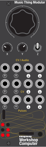 Level (Ch. 3)AttackReleaseMod 2Mod 3Mod 1PitchGBA SO (MISO)GateA button gateB button gateGate outQuantised pitchGBA SC (clock)GBA SI (MOSI)
Controls
Level (Ch. 3)
Level of channel 3 by default; assignable on the MAP page
Attack
Attack, both envelopes together, by default; assignable on the MAP page
Release
Release, both envelopes together, by default; assignable on the MAP page
Modulation: An eighth source on the GBA's MAP page - assign it to anything. Up is full, middle and down are zero
Trigger: Momentary down fires a note; a column of the GBA's TRIG grid
Inputs & Outputs
Inputs
Outputs
Inputs
Mod 2
Unassigned by default; assignable on the MAP page, with per-voice tickboxes
Mod 3
Unassigned by default; assignable on the MAP page, with per-voice tickboxes
Mod 1
Unassigned by default - nothing should move that you did not patch. Give it a job on the MAP page
Pitch
1V/oct pitch CV. Trim tracking on the GBA CAL page (CV inputs are not factory calibrated)
GBA SO (MISO)
Serial data back from the GBA. Read directly via PIO, not the 48kHz pulse path
Gate
Gate and trigger. Edges shorter than the 1ms poll are still caught
Outputs
A button gate
High while the GBA's A button is held - the performance gesture as a patchable voltage
B button gate
High while the GBA's B button is held
Gate out
5V while a note is sounding
Quantised pitch
The note the GBA is sounding, as calibrated 1V/oct. Turns the pair into a quantiser for the rest of the rack
GBA SC (clock)
Master serial clock driven by the RP2040 (PIO), inversion handled in hardware
GBA SI (MOSI)
Serial data to the GBA (payload upload, then the live input stream)
LEDs
Link (solid booted, blinking connecting)
Gate in / upload progress / fault code bit 0
Note sounding / upload progress / fault code bit 1
Editing on the GBA / upload progress / fault code bit 2
Edit page bit 0 / upload progress
Edit page bit 1 / upload progress
README
GBA — PSG Voice
Turns the Music Thing Workshop Computer into a Game Boy Advance link-cable master, and the GBA into a chiptune synth voice played by the modular. The module boots a cartridge-less GBA over the pulse jacks using BIOS Multiboot, then streams its inputs down a live SPI link. The GBA makes the sound on its own PSG hardware, out of its own headphone jack, and carries the whole editor on its own screen.
No cartridge, no flashcart, no modification to the console. The program is uploaded from the module every time you switch on, in about six seconds.
The division of labour is the design. The Workshop senses; the GBA is the instrument. This side reads eight inputs and sends them raw; the GBA owns pitch tracking, the modulation matrix, the envelopes, the ornaments, the drums and the UI. That is why the on-screen editor costs no protocol: re-mapping Audio In 1 from detune to vibrato is a table write in GBA RAM, not a firmware rebuild. Had the mapping lived on the Workshop side, every edit page would have needed its own downstream opcode.
Part 1 — Getting connected
What you need
| A Game Boy Advance | An original AGB-001 or a GBA SP. Note: The GBA SP does not have a headphone socket — it needs Nintendo's SP headphone adapter, which occupies the charging port. |
| No cartridge | Multiboot needs the slot empty. The console must sit on the Nintendo logo screen. |
| A link cable | See below. |
| 2 × 1 kΩ resistors | Any tolerance. These are not optional. |
Making the link cable
This is the only part of the build that can go wrong quietly, so it is worth doing carefully.
Use a Game Boy Color link cable
Get a Game Boy Color / Game Boy Pocket link cable rather than a third-party GBA one. The connector has been the same small six-pin part since the Game Boy Pocket, so a GBC cable plugs straight into a GBA — and, crucially, GBC cables are normally 6-core: every pin in the connector has a wire behind it.
That is the whole reason I prefer one. Third-party GBA cables are wildly inconsistent: many carry only the three or four conductors that particular cable's intended use needed, and which three varies. If the conductor you need is simply absent the fault looks exactly like bad wiring.
With six cores you know every signal is there before you start. You still have to find which is which but you are looking for something that exists.
The original DMG-era cable, with the big chunky connector, will not fit. You want the small connector introduced with the Game Boy Pocket.
The socket, and how it is numbered
Six pins in two rows of three. The shell is a hexagon with an asymmetric lump; pins 1 and 2 sit at the lump end. The numbering mirrors between plug and socket — the single easiest thing here to get wrong.
      PLUG (contacts toward you)          SOCKET (looking into the GBA)
    ┌──────────────────────────┐      ┌──────────────────────────┐
    │    1    3    5           │      │           5    3    1    │
    │        ╱▔▔▔╲             │      │            ╱▔▔▔╲         │
    │    2    4    6           │      │           6    4    2    │
    └──────────────────────────┘      └──────────────────────────┘
         lump at the top
Wiring
All directions are from the GBA's point of view, which is the only role we drive it in (multiboot slave).
| GBA pin | Signal | Workshop jack | RP2040 GPIO | Direction | Series R |
|---|---|---|---|---|---|
| 5 | SC (clock) | Pulse Out 1 | GPIO 8 | RP2040 → GBA | 1 kΩ |
| 3 | SI (MOSI) | Pulse Out 2 | GPIO 9 | RP2040 → GBA | 1 kΩ |
| 2 | SO (MISO) | Pulse In 1 | GPIO 2 | GBA → RP2040 | none |
| 6 | GND | ground | — | common | — |
| 1 | VCC +3.3 V | nothing — leave it floating | — | GBA output | — |
| 4 | SD | nothing | — | unused in SIO32 | — |
The two resistors, and the one that must not be there
1 kΩ in series on SC and SI. The Workshop's pulse outputs swing to about 6 V; the GBA's inputs are 3.3 V logic. The resistor, together with the GBA's own clamp diode, limits the current into the console. Skipping these could damage your GBA.
No resistor on SO. The GBA drives SO at 3.3 V into us, which the input handles as it stands.
Terminating it
Three options, in descending order of tidiness:
- A breakout PCB. I suggest this OSH Park shared project, with the two 1 kΩ resistors soldered onto the board. The cable solders to one side and the patch leads to the other, so the resistors are permanently where you cannot forget them.
- A female link socket on stripped board, cable into it, resistors inline.
- Bare wires, resistors soldered inline and heatshrunk. Works; label everything, because the wire colours mean nothing.
Whichever you choose, put the resistors where they cannot be left out by accident.
Before you plug a console in
- Check each conductor through to a named pin on the intact plug and write down the colour. Wire colours are not standardised — not even between official Nintendo production runs — so the table you fill in for your cable is the only record worth trusting.
- Check every pair against every other pair. You don't want shorts between pins and ground (which some GBA cables have with one of the pins).
The crossover — measure it, do not reason about it
If you make a dedicated cable by cutting a link cable, beware.
Peer-to-peer link cables generally swap SO and SI between their two ends, so the pin that carries SO at the end you kept depends on which end you kept — and you cannot tell the two ends apart by eye.
TO HELP YOU: build and flash cablecheck, then run MODE 0. It listens on Pulse In 1 and
Pulse In 2 at the same time and reports which wire actually carries the GBA's SO.
cmake -G Ninja -B diagnostics/build -S diagnostics
cmake --build diagnostics/build --target cablecheck   # -> diagnostics/build/cablecheck.uf2
Continuity tables and notes on specific cables are in
diagnostics/CABLES.md.
First power-up
Power the Computer first, then the GBA. The console only syncs if the master is already clocking when it boots.
- Flash
gba_link.uf2to the Workshop Computer. - Remove any cartridge from the GBA. Connect the cable.
- Power the Workshop. LED 0 blinks — it is looking for a console.
- Switch the GBA on. It shows the Nintendo logo, then goes plain green — that green screen is the payload's own code running, and is your proof the upload worked.
- LEDs 1–5 sweep as a progress bar for about six seconds.
- The GBA lands on the performance screen. LED 0 goes solid. Push the Workshop Computer's momentary switch down and you should hear a note.
If it does not work
While the link is not up, LED 0 blinks and LEDs 1–3 report the last multiboot result as a three-bit code:
| LEDs lit | Meaning | Look at |
|---|---|---|
| 1 | NoGBA — nothing answered at all | Power order. Cartridge removed? Is the GBA on the logo screen? Ground. Then the crossover. |
| 2 | BadHandshake — it answered, then the exchange went wrong | Marginal wiring, a missing series resistor, or a poor ground. |
| 1 + 2 | TransferError — a data word's echo did not match | Noise or a bad joint on SI/SC. Check for shorts. |
| 3 | CrcMismatch — it all arrived, but corrupted | As above; usually a marginal connection rather than a wrong one. |
| 1 + 3 | BadPayload | A build problem, not a wiring one. Rebuild the payload. |
NoGBA is by far the most common, and its most common cause is not wiring — it is a console that was already running the payload from a previous session.
For a step-by-step bring-up that isolates one thing at a time, work down
BENCH.md. Each step tells you where a failure is rather than just that there is
one.
Part 2 — Playing it
Well done for getting this far!
Audio
Patch the GBA's headphone jack into Eurorack if you wish, but NOTE the headphone ground on the GBA SP adapter may short the signal with a shared ground. If so, use a ground-isolating stereo audio cable.
Expect it to be quiet: around 1 Vpp against Eurorack's ~10 Vpp, so it wants a mixer channel or the next module's input rather than going straight to an output.
The default patch
The default patch has every jack, knob and button doing something audible from the first note, and the module's own switch triggers it, so you can hear it work with nothing patched at all.
| Channel 1 | left, 50 % duty, 10 ms attack, fast portamento |
| Channel 2 | right, 25 % duty, 250 ms attack, no portamento, +2 detune |
| Channel 3 | both sides, sine on a permanent octave trill, level under the Main knob |
| Channel 4 | off — the DRUM page is where noise earns its place |
The pair arrives from different sides at different times, which is most of why it sounds wide.
| Control | Does |
|---|---|
| Switch down | trigger |
| CV In 2 | 1V/oct pitch |
| Main knob | level of channel 3 |
| X knob | attack, both envelopes together |
| Y knob | release, both envelopes together |
| A / B | trigger / hold |
| L | cycle both duty cycles |
| R | cycle channel 1's sweep time |
| D-pad ↑ ↓ ← → | ornament: major chord, minor chord, octave drop-and-leap, chromatic run |
The D-pad ornaments apply to the melodic pair only, so channel 3 keeps its trill underneath while the lead switches figures. Up and Down loop; Left and Right are one-shots.
Pulse In 2, CV In 1 and both Audio Ins are deliberately unassigned — nothing should move that you did not patch. The MAP page is where you give them a job.
The panel
| Jack | Default role | Re-assignable? |
|---|---|---|
| CV In 2 | 1V/oct pitch | yes, MAP page |
| Pulse In 2 | gate / trigger | TRIG page |
| CV In 1 | unassigned | yes, MAP page |
| Audio In 1 | unassigned | yes, MAP page |
| Audio In 2 | unassigned | yes, MAP page |
| Main knob | level of channel 3 | yes, MAP page |
| X / Y knobs | attack / release | yes, MAP page |
| Switch (down) | trigger | TRIG page |
| Switch (up) | unassigned modulation | yes, MAP page |
| CV Out 2 | quantised pitch, calibrated 1V/oct | — |
| CV Out 1 | gate out, 5 V | — |
| Audio Out 1 / 2 | GBA A and B buttons as gates | follows the BTN page |
CV Out 2 makes the pair a quantiser for the rest of the rack. ComputerCard calibrates the CV outputs from the module's EEPROM, so the pitch coming out is in tune without any trimming — set a scale on the SET page and the rest of your rack can play from it.
Audio Out 1 and 2 send your performance gestures back out. Mult A into another module's trigger input and it follows your fingers.
LEDs while the link is up: 0 link, 1 gate in, 2 note sounding, 3 editing, 4+5 edit page as a binary pair.
Part 3 — The editor
START opens the editor, and lands on MEM. Recalling a patch is the one editor action that happens mid-performance, so it is one gesture away rather than eight presses of SELECT.
Inside the editor no button carries its performance meaning — not trigger, not hold, not the mapped D-pad actions. Those belong to the performance screen. HOLD set before you enter still holds, so you can latch a drone in PLAY and then go and edit it while it sounds.
| D-pad alone | move the cursor (row, and on grid pages a column) |
| A + Up/Down | change the value |
| A + Left/Right | change coarsely, or the row's second field |
| SELECT + Left/Right | change page — hold it down to run through them quickly |
| START | back to the performance screen |
MEM — sixteen patch slots
The grid is the page. D-pad picks a slot — left/right by one, up/down by eight. A + Up saves. A + Down loads. A progress bar runs during the transfer; a slot that holds nothing says so rather than loading silence.
Slots live in the RP2040's flash, not the GBA — the console's RAM is wiped every time it is switched off, so the Workshop is where a patch has to persist.
Saving clicks the audio. Erasing flash stops execution-in-place, so the 48 kHz callback is parked for the few milliseconds the write takes. That is the price of a deliberate action, and the reason patch storage is not something the audio path does.
A + Up saves to whatever slot the cursor is on. Since START now lands here, be aware that START followed by an idle A + Up will overwrite.
CHAN — all four channels at once
A grid: ten parameters down, four channels across. [X] marks a cell that does not apply to
that channel — detune is channel 2's alone, the sweep belongs to channel 1, noise pitch and
ratio to channel 4.
| Row | |
|---|---|
| OUTPUT | OFF / L / R / BOTH |
| SEMITONE | ±24, per channel — the pitched three |
| ORNAMENT | OFF, slots 1–6, or CV (chosen live by a mapping) |
| TIMBRE | one idea, four spellings: duty for the squares, waveform for channel 3, noise type for channel 4 |
| DETUNE | channel 2 only, in 1/16-semitone steps |
| N PITCH / N RATIO | channel 4's noise generator |
| SWP TIME / DIR / DEPTH | channel 1's frequency sweep |
Channel 3's twelve waveforms: SINE, TRI, SAW UP, SAW DN, SQUARE, PULSE 12, PULSE 25, ORGAN, HALF SIN, BELL, VOX, STEPS.
TRIG — what fires what
A pin grid, not a switch: three trigger sources (PU2, the Workshop SWitch, a mapped GBA BTN) against four channels. Tick any combination.
Channel 1 can fire from the switch and Pulse In 2 while channel 2 fires from the switch only. A channel wired to nothing is deliberately silent, and HOLD does not override that.
ENV — per-channel ADSR
CHANNEL, ATTACK, DECAY, SUSTAIN, RELEASE, PORTAMENTO, RETRIGGER, with the envelope
drawn as you edit it and a live tick showing where the note currently sits.
Times run 0, 5, 10, 20, 35, 60, 100, 160, 250, 400, 650 ms, then 1, 1.6, 2.5, 4, 6 seconds — spread over what you would actually dial rather than a plain power-of-two ladder.
PORTAMENTO is per voice, which is what lets channel 1 slide while channel 2 steps.
MIX — levels and panning
Four faders: level 0–15 and OFF / L / R / BOTH, with the live envelope drawn inside the set level so you can see the envelope working against the ceiling you gave it.
BTN — what the eight GBA buttons do
One row each for A, B, L, R and the four D-pad directions. Twenty-five actions. The ones whose scope is not obvious from the name:
| Action | Applies to |
|---|---|
TRIGGER / HOLD |
whichever channels tick BTN on the TRIG page |
ORN SLOT 1–6 |
channels 1 and 2 only — the melodic pair, so channel 3 keeps its own figure underneath |
SWEEP TIME |
channel 1 only; cycles 0–7, one step per press, 0 being off |
DUTY 1 / DUTY 2 |
that square, cycling 12.5 → 25 → 50 → 75 % |
DUTY BOTH |
both squares together, so they stay locked rather than drifting apart |
OCT + / OCT - |
global (±3) — every channel moves, including noise if it tracks pitch |
ORNMNT + / - |
all four channels, each stepped by one from wherever it is, so relative offsets survive |
SEMI + / - |
all four channels |
CH1–CH4 ON/OFF |
mutes that channel |
These edit the patch itself, so they survive into a save — they are real changes, not temporary performance offsets.
MAP — the modulation matrix
Eight sources, each with a destination, an amount, and per-voice tickboxes.
Sources: CV 1, CV 2, AUD 1, AUD 2, MAIN, KNOB X, KNOB Y, SWITCH.
Destinations: PITCH, LEVEL, DUTY, DETUNE, GLIDE, DECAY, SWEEP, N PITCH, ORNMNT, ORNRATE, SCALE, KEY, ATTACK, RELEASE.
The four jacks are bipolar around 0 V; the three knobs are unipolar and are centred internally, so one amount control means the same thing for both. The switch is neither — UP is full, MIDDLE and DOWN are zero. Down is already a trigger gesture, and giving it a modulation value too would mean every trigger also yanked whatever it was mapped to.
For PITCH, an amount of +32 is unity 1V/oct.
Ornament mappings are switches, not depths. When the destination is ORNMNT the amount
column names the slot, and the source is on above halfway. There is no forty per cent of an
arpeggio.
ORN — ornaments
Six slots of up to sixteen semitone offsets, edited graphically. SLOT, LENGTH, RATE,
MODE (loop while held, or one-shot then hold the last step) and the step editor.
On the steps row, L/R moves between steps, A + Up/Down moves by a semitone, A + L/R by an
octave. A channel set to CV on the CHAN page takes whichever slot a mapping selects, so a
knob or a gate can switch figures live.
DRUM — noise and percussion
DRUM MODE, THRESHOLD, then one row per input: AUD 1, AUD 2, CV 1, CV 2, PU 2, SWITCH. Any
input going high fires its sound. Eleven presets: KICK, SNARE, CL HAT, OP HAT, TOM HI, TOM LO,
RIM, CLAP, COWBELL, ZAP.
Drums borrow channels 3 and 4, so both squares stay melodic — two squares is a lead and a bass, which is the better half of the machine to keep.
CAL — trimming 1V/oct
CV SCALE, CV OFFSET, BASE NOTE, MASTER L, MASTER R, PSG LEVEL, CV 2 IN, LINK.
This page is not filler, and you will need it. ComputerCard calibrates the CV outputs from
the module's EEPROM, so the quantised pitch coming out is in tune for free — but there is no
calibration of any kind for the CV inputs. 1V/oct tracking on CV In 2 rests on a single
constant, CV SCALE, and it varies with the module.
CV SCALE is counts per semitone in 1/256ths. CV 2 IN shows the live raw count — the
exact number the pitch maths works on — and it is what makes an accurate trim possible instead
of a hunt by ear.
The two-point trim
- Patch your pitch source to CV In 2 and open the CAL page.
- Play a low note and read
CV 2 IN. Call it L. - Play a note exactly two octaves higher and read it again. Call it H.
CV SCALE= 256 × (H − L) ÷ 24, since two octaves is 24 semitones. Two octaves rather than one because the arithmetic error halves.- Dial that in on
CV SCALE— A + Left/Right steps by 64, A + Up/Down by 1 — and re-check by ear.
CV OFFSET then moves the whole range without changing its span, and BASE NOTE sets what
0 V means (C2 by default).
The live tuner
Below the list, two lines update as you patch:
IN  C3 +07c   RAW  2048
OUT C3        CAL
IN reads CV In 2's raw voltage straight through the current calibration — note name plus
cents, at unity depth and ignoring any scale or key — so it moves the instant you nudge CV SCALE or CV OFFSET, without needing a note to actually sound. OUT is the note really
playing on channel 1 right now, after the modulation matrix and any scale quantising.
Patch a running sequence into CV In 2 and watch both at once: trim until IN reads dead on
(0c) at each step, and check OUT matches what you expect — if it does not, a scale or key is
quantising it there on purpose, which is worth knowing before you conclude the calibration is
wrong. RAW is unchanged from before and is what the two-point trim above still reads.
The shipped default of 7422 is a bench measurement, not a specification — expect to trim it on yours. It's the one of three readings that actually plays in tune on this module: 3312 (from an earlier module) and 3372 (a refinement of that) were both tried and both sounded audibly worse here. A plausible-looking number from another unit, or from theory, is not a substitute for the two-point trim below on the one in front of you.
Why the constant is stored so finely. Pitch error accumulates with distance from the calibration point, so a coarse constant is not a small error at the far end of the keyboard. In 1/16ths one step was 0.48 %, which is 17 cents three octaves up — correct fell between two adjacent values with nothing in between. In 1/256ths the same step is 1.1 cents. None of this involves floating point: the maths was always integer, and the resolution is simply how many bits the stored constant carries.
Nothing on the Workshop side needs changing to fix tracking. That end sends raw ADC counts and nothing else, by design; every part of the pitch calculation lives on the GBA, which is why this is a number you can dial rather than a firmware rebuild.
SET — tuning, key and scale
TUNING (master, in cents), KEY, SCALE, OCTAVE, and the user-scale editor.
Twenty scales: FREE, then CHROMATIC, MAJOR, DORIAN, PHRYGIAN, LYDIAN, MIXOLYD, MINOR, LOCRIAN, HARM MIN, PENTA MAJ, PENTA MIN, BLUES, HIRAJOSHI, IN SEN, WHOLE, then USER 1–4.
FREE is first, and the factory default. It quantises nothing at all: pitch passes through exactly as the calibrated CV reads it, fractional cents and all, all the way to the PSG's period register — the setting for a CV source that should glide continuously (an envelope, an LFO, a slide generator) rather than being pulled onto a grid of any kind. CV Out 2 keeps reporting the nearest whole semitone regardless of this setting, since it has no way to carry a fraction of one.
CHROMATIC still quantises — to the nearest semitone, with all twelve degrees valid — and any other built-in or user scale narrows that to its own degrees. Because the quantiser snaps the target, portamento still glides into it rather than being stepped away.
To edit a user scale, select USER 1–4 and move to SCALE NOTES: the twelve semitones are drawn
as a row of toggles. CHROMATIC shows BUILT IN there and FREE shows N/A — neither has degrees
to edit.
Part 4 — Reference
Musical behaviour worth knowing
The noise channel tracks pitch, but only in octaves. Its frequency is 524288 / r / 2^(s+1),
so the shift field steps by a factor of two and nothing finer — the eight divider ratios do
subdivide an octave, but unevenly, so there is no honest chromatic mapping to be had. Tick
channel 4 on a PITCH mapping and it follows an octave at a time, which is what tuned noise
percussion has always meant on this hardware.
Channel 3's level is applied by scaling its wavetable, not its volume register. The hardware register offers only mute / 25 / 50 / 100 %, far too coarse for an envelope; scaling the samples gives a full sixteen steps. If a control on channel 3 ever seems to do nothing, suspect its volume register first — it is coarser than anything else on the instrument.
Sweep and a software envelope do not fully coexist. Every envelope step retriggers the channel, and a retrigger reduces channel 1's sweep — so a sustained level is where a sweep gets to run. This is a property of the hardware, not a bug.
No Direct Sound, no DMA. Real sample playback would need a timer, the FIFOs, and sample data in an already six-second payload.
How it works
- Multiboot upload. The RP2040 runs the documented single-cartridge handshake (sync → header
→ palette/handshake → encrypted payload → CRC) and streams the program into the GBA's EWRAM.
See
gba_multiboot.cpp.0xC0must hold a BRANCH, not code — the BIOS overwrites bytes0xC4and0xC5of the loaded image. - Live link. After boot the RP2040 polls at 1 kHz, sending the inputs and receiving
buttons, note and status framed by a 16-bit tag. See
gba_proto.handgba_link.cpp. The inter-word gap is what matters, not the clock: the slave holds one pending transfer and re-arms with a read-modify-write, so a poll landing early corrupts the word rather than merely wasting it. 2000 words/s is measured clean, so 1 kHz runs at half the proven rate. - Two cores. ComputerCard's 48 kHz audio/CV loop runs on core 0; the entire link engine
runs on core 1 and talks to core 0 only through the lock-free
GbaSharedstruct. - Serial IRQ. The GBA re-arms its slave from the serial interrupt, so it is not deaf while it redraws — with the polled path kept as a live fallback. The CAL page reports which is running.
- PIO SPI with baked-in inversion. The pulse jacks are hardware-inverted and GPIO 8/9/2
aren't hardware-SPI pins, so the transfer is a PIO state machine (
gba_spi.pio, mode 3, MSB-first, 32-bit). Pulse In 1 inverts — established by the GBA's own reply, not by inference.
Bring-up was not straightforward. If you are going to touch the transport, read
diagnostics/POSTMORTEM.mdfirst. Several days went into faults that turned out to be in the diagnostics rather than the hardware.
Patch storage
Sixteen slots in the last flash sector of the RP2040 — 256 bytes each, one sector, because the sector is the erase unit. A transfer is one byte per link word, each carrying its own index, so a dropped word leaves a hole the receiver can see rather than silently shifting everything after it. A save repeats the whole block until the host acknowledges; the host only ever commits a complete one.
Patches carry a version. A patch saved by an older firmware whose layout has since changed is
rejected with BAD DATA - NOT LOADED rather than loaded as garbage.
Building
RP2040 firmware (SDK 2.2.0, toolchain 14_2_Rel1):
cmake -G Ninja -B build -S .
cmake --build build          # -> build/gba_link.uf2
GBA payload → gba_payload.h:
cd payload && ./build.sh # then rebuild the firmware
build.sh needs no devkitPro: it uses the Pico SDK's own arm-none-eabi-gcc and a bundled
dependency-free gbafix.py to insert the Nintendo logo and fix the header complement, both of
which the GBA BIOS validates. See payload/README.md.
Files
| File | Role |
|---|---|
main.cpp |
ComputerCard subclass (core 0): reads the inputs, drives CV/gate out, LEDs |
gba_proto.h |
The wire protocol, shared verbatim by both sides |
gba_link.h / .cpp |
Core-1 link engine + GbaShared cross-core state |
gba_multiboot.h / .cpp |
Multiboot uploader + progress |
gba_spi.pio / gba_spi.h |
PIO SPI master transport (GPIO 8/9/2) |
patch_store.h / .cpp |
Sixteen patch slots in the RP2040's flash |
payload/link.c |
GBA serial slave, serial IRQ, protocol decode, patch transfer |
payload/psg.c |
PSG registers, twelve wavetables |
payload/synth.c |
Voice model: pitch, modulation, envelopes, ornaments, drums |
payload/ui.c |
Performance screen + eleven-page editor |
payload/diag.c |
Link-characterisation screens (linkrate / bandwidth) |
ComputerCard.h |
Vendored HAL (Chris Johnson's library, with Andy's fixes) |
| Document | |
|---|---|
BENCH.md |
Step-by-step bring-up. Start here if it does not work |
diagnostics/ |
Ten link diagnostics and the notes behind them — see its README |
diagnostics/CABLES.md |
Cable continuity tables, per cable type |
diagnostics/TESTPLAN.md |
Bench procedure |
diagnostics/POSTMORTEM.md |
What went wrong during bring-up, and how each fault was caught |
The diagnostics ship with the release on purpose. The link runs over jacks that were never meant to carry SPI, through a cable whose internal wiring is not standardised, and the failures are silent — a transposed pair, a missing conductor and a console that simply is not listening all present as "nothing happens". Guessing between those is expensive; measuring is not. They also reuse the applet's own transport, so a pass exercises the real code path rather than a simulation of it.
Credits & references
By Andy Jenkinson, 2026. Built on Chris Johnson's ComputerCard HAL for Tom Whitwell's Music Thing Workshop Computer.
Multiboot protocol and constants transcribed from the public open-source references akkera102/gba_01_multiboot and the RP2040 port in copyrat90/gba-pico-gamepad; the PIO SPI core follows the Raspberry Pi pico-examples SPI CPHA=1 program. Register details throughout from GBATEK.
MIT licensed.