
111 8mu CV
A playable, unpredictable instrument as much as a showcase for the Music
Thing 8mu: every control it has - the eight faders, the four top buttons,
and the accelerometer - drives the Workshop Computer's outputs. Set the LFOs
running and latch in the accelerometer, and the controller steers voltages,
rates and widths you didn't quite dial in - surprising, and often musical.
It is also a way to test an 8mu channel by channel. The audio outputs are
DC-coupled, so they carry steady voltages just as well as sound, giving four
bipolar voltage sources rather than the usual two.
Faders 1-4 set the levels of Audio Out 1, Audio Out 2, CV Out 1 and CV Out
2, each running from about -5V at the bottom through 0V in the middle to
about +5V at the top. Faders 5 and 6 set the rates of Pulse Out 1 and Pulse
Out 2: independent pulses from 0.1Hz to 20Hz, exponential across the fader
so equal movements multiply the rate. Faders 7 and 8 set their widths: the
middle is a 50% square, the way down narrows toward a sharp trigger, the way
up widens toward a gate that stays open nearly all the time.
The Computer's switch picks the mode. Middle is the basic card. Up is LFO
mode: a tap on a top button arms that output, capturing the voltage it is
already at as the centre for a triangle LFO, with the fader then setting the
speed. The Main knob sets how far the triangle swings, always measured to
the nearer supply rail, so it can never clip.
Holding the switch Down for half a second latches the accelerometer on or
off. When it is on, the four gesture axes take over the four voltage outputs
and their LFO rates: Pitch and Roll (tilt), Yaw (spin), and Flip (which way
up, unipolar so a flat 8mu reads 0). The X knob scales how far the gestures
respond and the Y knob smooths them. The three panel knobs are otherwise
not a fallback, since the point of the card is to drive the 8mu; unplug it
and the outputs hold their last values.
The card is a pure MIDI listener: it never writes to the 8mu's LEDs or
settings, so the controller behaves exactly as it does anywhere else. It
needs a Rev 1.1 or later Computer, and nothing else may be in the front USB
socket, because the Computer has to act as a USB host.
Panel
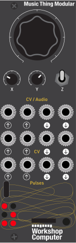 LFO depthGesture sensitivityGesture smoothingVoltage 1Voltage 2Voltage 3Voltage 4Pulse 1Pulse 2
Controls
LFO depth
How far the triangle LFOs swing, fully anticlockwise for no swing to fully clockwise for the whole distance to the nearer supply rail. Always measured to the rail, so an LFO can never clip. Only affects outputs that are armed.
Gesture sensitivity
How far the accelerometer gestures respond, exponential from about 0.25x to 4x across the knob. Only applies while the accelerometer is latched on.
Gesture smoothing
How much the accelerometer gestures are smoothed, from barely any to a settled ~20ms glide. Softens a shaky hand while the accelerometer is latched on.
LFO: Outputs armed with a top button oscillate as triangle LFOs, with their faders setting the rate. Outputs that are not armed stay steady voltages. The Main knob sets the LFO swing depth.
Basic: Faders 1-4 are steady voltages and faders 5-8 are pulse rate and width. Any output that was oscillating in LFO mode glides back to its captured centre.
Latch accelerometer: Momentary. Held for about half a second, it latches the accelerometer on or off. When on, the four gesture axes take over the four voltage outputs and their LFO rates. All six LEDs blink on the change.
Inputs & Outputs
Inputs
Outputs
Inputs
Outputs
Voltage 1
Bipolar voltage from fader 1, about -5V to +5V with 0V at the middle of the fader. Uncalibrated. The audio outputs are DC-coupled, so this carries a steady voltage as happily as sound. Top button 1 arms it as a triangle LFO in LFO mode. With the accelerometer latched on, Pitch drives it instead.
Voltage 2
Bipolar voltage from fader 2, same range as Voltage 1. Top button 2 arms its LFO; Roll drives it with the accelerometer latched on.
Voltage 3
Bipolar voltage from fader 3, same range as Voltage 1. Top button 3 arms its LFO; Yaw drives it with the accelerometer latched on.
Voltage 4
Bipolar voltage from fader 4, same range as Voltage 1. Top button 4 arms its LFO; Flip (unipolar, flat = 0) drives it with the accelerometer latched on.
Pulse 1
Rate set by fader 5, 0.1Hz to 20Hz with an exponential response - a slow LFO at the bottom of the fader, a fast rhythmic gate at the top. Width set by fader 7: centre is a 50% square, down narrows toward a sharp trigger, up widens toward a gate. Always a pulse, never dead.
Pulse 2
Rate set by fader 6 and width by fader 8, independent of Pulse 1.
LEDs
8mu
Lit while a USB MIDI controller is connected.
Voltage 1
Brightness follows the level of Audio Out 1.
Pulse 1
Follows Pulse Out 1 on and off.
Pulse 2
Follows Pulse Out 2 on and off.
LFO mode
Lit while the switch is up, selecting LFO mode.
Voltage 3
Brightness follows the level of CV Out 1.
README
8mu CV
A Music Thing 8mu driving four voltages, two pulses, and an accelerometer.
8mu CV turns a Music Thing 8mu into a playable front end for the Workshop Computer. Every control the controller has, the eight faders, the four top buttons and the accelerometer, ends up on the Computer's jacks: four voltages and two pulse streams. Arm the LFOs and latch in the accelerometer, and tilting or turning the controller steers levels, rates and widths you did not dial in. That is where the music tends to come from. It is easy to set something in motion and then be surprised by it.
It is also a quick way to test an 8mu channel by channel. It is meant to be used with the 8mu: unplug it and the outputs hold their last values.
Controls
Faders
| Fader | Jack | What it does |
|---|---|---|
| 1 | Audio Out 1 | Voltage, centre 0V (or LFO rate) |
| 2 | Audio Out 2 | Voltage, centre 0V (or LFO rate) |
| 3 | CV Out 1 | Voltage, centre 0V (or LFO rate) |
| 4 | CV Out 2 | Voltage, centre 0V (or LFO rate) |
| 5 | Pulse Out 1 | Rate, 0.1Hz to 20Hz |
| 6 | Pulse Out 2 | Rate, 0.1Hz to 20Hz |
| 7 | Pulse Out 1 | Width, centre is a 50% square |
| 8 | Pulse Out 2 | Width, centre is a 50% square |
Top buttons
| Button | Jack | What it does |
|---|---|---|
| 1 (C2) | Audio Out 1 | Arm/disarm its LFO |
| 2 (C3) | Audio Out 2 | Arm/disarm its LFO |
| 3 (C4) | CV Out 1 | Arm/disarm its LFO |
| 4 (C5) | CV Out 2 | Arm/disarm its LFO |
Switch and panel knobs
| Control | Job |
|---|---|
| Switch Middle | Basic: faders 1-4 are steady voltages, 5-8 pulse rate and width |
| Switch Up | LFO: armed outputs oscillate |
| Switch Down | Momentary; hold about 0.5s to latch the accelerometer on or off |
| Main | LFO depth |
| X | Gesture sensitivity |
| Y | Gesture smoothing |
The 8mu is the only source of the eight parameters. The panel knobs are not a fallback; each has one job above.
Patching it
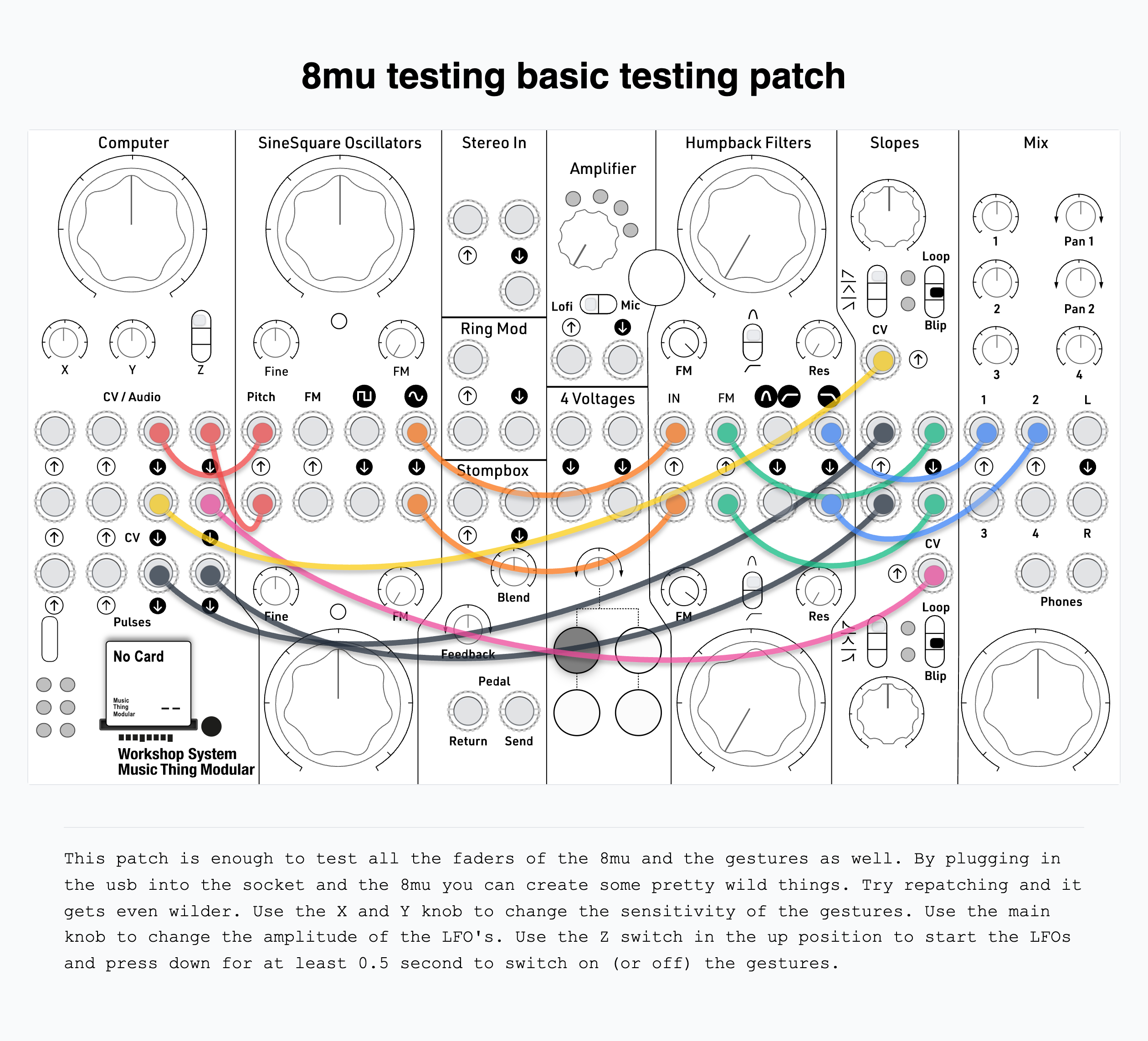
The card is a voltage and pulse source, so it goes wherever those go: oscillator pitch, filter cutoff, VCA level, a wavefolder's bias, clocks and gates.
Modes
The Computer's switch picks what the card does:
| Switch | Mode | Behaviour |
|---|---|---|
| Middle | Basic | Faders 1-4 are steady voltages, 5-8 pulse rate and width |
| Up | LFO | Armed outputs oscillate; un-armed outputs stay steady voltages |
| Down (momentary) | Latch | Held about half a second, it latches the accelerometer on or off |
Switching back to Middle stops any oscillation, and each output glides to its captured centre rather than jumping.
The voltages
Each of the four voltage outputs follows its fader from about -5V at the bottom, through 0V in the middle, to about +5V at the top. The audio outputs are DC-coupled on this hardware, so Audio Out 1 and Audio Out 2 carry a steady voltage just as well as sound. That gives four independent voltage sources rather than the usual two from two CV jacks. None of them are calibrated, which does not matter here: this card is a source of control voltages, not a pitch reference.
The level is smoothed a little, so the steps in the 8mu's 7-bit faders do not click into whatever the voltage is controlling.
LFOs
Any of the four voltage outputs can be a triangle LFO instead of a steady voltage. A tap on one of the top buttons arms that output; it oscillates while the switch is Up. You can arm in Middle and flip Up to hear it.
Arming captures the voltage the output is already sitting at as the centre to swing around. While it is oscillating, the fader that set the level sets the rate instead: 0.1Hz to 20Hz, exponential, the same feel as the pulse rates. So the move is: dial in a voltage, tap the button, flip Up, and it comes alive around that point while your finger takes over the rate.
An output that is not armed is still a steady level even in LFO mode, so the card stays useful with one LFO running, or none.
Main sets how far the triangle swings. Fully anticlockwise is almost no swing, a bare trace; fully clockwise is the whole distance to the nearer supply rail. The swing is measured to the rail, so it scales itself down as the centre gets close to one, and an LFO can never clip. Main only affects armed outputs.
Disarming an output, by tapping its button again or dropping the switch back to Middle, glides it to its centre. The fader does not grab the level back immediately, because it is sitting at a rate position. It stays locked until you move it to meet the captured value, so nothing jumps.
Holding any one of the four buttons for a second and a half disarms all four at once. That is the quick way to stop everything.
Arming survives the 8mu being unplugged, and the mode belongs to the switch, so there is always a way back to steady voltages from the panel.
The accelerometer
Hold the switch Down for about half a second to latch the accelerometer on or off. All six LEDs blink to confirm. It is off by default. When it is on, the four gesture axes replace the four voltage faders and their LFO rates:
| Axis | Output | Feel |
|---|---|---|
| Pitch | V1 | tilt, back lifted positive; bipolar, rests at 0V / mid rate |
| Roll | V2 | tilt, right lifted positive; bipolar, rests at 0V / mid rate |
| Yaw | V3 | spin, clockwise positive; bipolar (a rate of turn), rests at 0V / mid rate |
| Flip | V4 | which way up; unipolar, flat = 0V / slowest, upside-down = max / fastest |
In Basic the axis sets a steady voltage. In LFO mode an armed output's axis sets its rate instead, replacing the fader. The X knob scales how far the gestures respond, exponential from about 0.25x to 4x. The Y knob smooths them, so a shaky hand does not judder the output. The latch survives the 8mu being unplugged.
The pulses
Pulse Out 1 and Pulse Out 2 are independent pulse streams. Fader 5 and fader 6 set their rates between 0.1Hz and 20Hz, with an exponential response, so equal movements of the fader multiply the rate by the same amount. That matches the way speed is heard: the bottom of the fader is a slow blink, the top is a fast pulse.
Fader 7 and fader 8 set the width, how much of each cycle the output stays high. The middle of the fader is a 50% square; up widens it, down narrows it.
| Width fader | Duty | Good for |
|---|---|---|
| Bottom (~2%) | very narrow | a sharp trigger or clock edge |
| Middle (50%) | square | the classic LFO / gate shape |
| Top (~98%) | very wide | a gate that holds a note or envelope open nearly all the time |
The width never quite reaches zero or full, so there is always a pulse being produced, never a dead or stuck output. Like the voltages, the width is smoothed slightly, so sweeping the fader does not stretch a single pulse as it passes.
Patch the pulses into clocks, triggers, gates, or anything that wants a rhythmic on/off. At the bottom they are slow enough to use as an LFO; narrow them for triggers and widen them into gates.
Without a controller
Unplug the 8mu and the outputs simply hold their last values. Nothing new can be set, but nothing jumps either. The switch still selects the mode, so an armed output can still be stopped from the panel. Plug the controller back in and its faders take over again.
Panel LEDs
| LED | Meaning |
|---|---|
| 0 | Lit while an 8mu is connected |
| 1 | Brightness follows the Audio Out 1 level |
| 2 | Follows Pulse Out 1 |
| 3 | Follows Pulse Out 2 |
| 4 | Lit in LFO mode (switch up) |
| 5 | Brightness follows the CV Out 1 level |
All six blink briefly when the accelerometer latch is toggled.
Requirements
The 8mu is a USB device, so the Computer has to act as a USB host. This needs a Rev 1.1 or later board, and nothing else may be plugged into the Computer's front USB socket. The card never drives the 8mu's LEDs, so the controller behaves as it does anywhere else.
Building
cmake -B build -G Ninja
cmake --build build
Drag build/8mu_cv.uf2 onto the Pico in bootloader mode, or use the binary committed at UF2/8mu_cv.uf2.
Credits
- Chris Johnson — the ComputerCard library and
EightMU.h, which carries the USB MIDI host driver and the TinyUSB host configuration. - rppicomidi — the
usb_midi_hostdriver, MIT, vendored insideEightMU.h. - Tom Whitwell / Music Thing Modular — the Workshop System and the 8mu.
License
MIT. See LICENSE, which records the vendored components and their terms.