
57 Glitch
A clock-synced beat-repeater with two power-on modes sharing one 2.33-second circular buffer. Glitch mode loops ratcheted sub-slices of the last beat with optional reverse, decimation and bitcrush; Stutter mode slices the beat and shuffles or repeats slices in real time. Pulse In 1 sets beat length, CV In 1 freezes recording while playback continues, and Audio Out 2 stays dry for parallel routing.
Panel
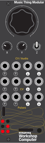 Zone / ProbabilityDegrade / ShuffleDegrade Probability / RepeatMain Audio InputFreeze CVMod CVClock InputExternal GateProcessed OutputDry OutputActivity GateDescending RampSlice ClockClock Mirror
Controls
Zone / Probability
Selects the ratchet zone (Glitch — 1, 2, 3, 4, 6) or slice zone (Stutter — 1, 2, 3, 4, 8), with position within the zone setting reverse probability (Glitch) or drift probability (Stutter)
Degrade / Shuffle
Glitch mode sets the degradation amount (decimation then bitcrush); Stutter mode sets the shuffle probability
Degrade Probability / Repeat
Glitch mode sets the degradation probability; Stutter mode sets the repeat probability before a slice advances
Probabilistic: Effect triggers randomly against the probability threshold. Held at power-on (or left unheld) this also selects Glitch mode.
External Gate: Effect triggers while Pulse In 2 is high. Held at power-on this also selects Glitch mode.
Force: Effect applies to every slice. Held at power-on this selects Stutter mode instead of Glitch mode.
Inputs & Outputs
Inputs
Outputs
Inputs
Main Audio Input
Source audio for buffering and processing
Freeze CV
Above approximately 0V stops recording and loops frozen buffer content
Mod CV
Bipolar modulation added to performance knobs — Glitch mode adds to X and Y, Stutter mode adds to X only
Clock Input
Rising edge defines beat length (max 2.33 seconds)
External Gate
Gate control for switch-middle trigger behaviour in both modes
Outputs
Processed Output
Glitched/stuttered output, or pass-through when the effect is inactive
Dry Output
Always a dry pass-through of Audio In 1
Activity Gate
High while glitch/shuffle is active, low during pass-through
Descending Ramp
Falls across each slice and resets at the slice boundary
Slice Clock
Pulse at each ratchet/slice boundary
Clock Mirror
Direct mirror of Pulse In 1
LEDs
Zone Indicator
Lit when the first ratchet/slice zone is selected
Zone Indicator
Lit when the second ratchet/slice zone is selected
Zone Indicator
Lit when the third ratchet/slice zone is selected
Zone Indicator
Lit when the fourth ratchet/slice zone is selected
Zone Indicator
Lit when the fifth ratchet/slice zone is selected
Probability Indicator
Brightness indicates the probability threshold — reverse in Glitch mode, drift in Stutter mode
README
Glitch records into a shared 2.33-second circular buffer and runs in one of two modes, chosen at power-on by the switch position.
Choosing a mode. Hold the switch in the desired position while the card powers on or resets: Middle or Up (or not held) loads Glitch mode; Down loads Stutter mode. A boot animation confirms the mode — Glitch flashes LEDs 0, 2, 4 in sequence three times; Stutter flashes LEDs 5, 3, 1 in reverse three times. Once the mode has latched (about 100 ms after power-on) the switch reverts to its live performance role in both modes.
Glitch mode. On each clock pulse the beat length is measured and a ratcheted sub-slice of that beat is replayed, optionally reversed and degraded with sample-rate reduction then bitcrushing. Main selects the ratchet zone (1, 2, 3, 4, 6) and the reverse probability within that zone; X sets the degradation amount and Y the degradation probability. CV In 2 adds bipolar modulation to both X and Y. When not glitching, live audio passes through unaffected.
Stutter mode. A live breakbeat slicer. Main selects the slice zone (1, 2, 3, 4, 8) and the drift probability within that zone; X sets the shuffle probability and Y the repeat probability, which governs how often a slice repeats before advancing. CV In 2 adds bipolar modulation to X only.
Shared behaviour. In both modes the switch selects how the effect is triggered: Up is probabilistic, Middle is gated from Pulse In 2, and Down forces the effect on every slice. CV In 1 above roughly 0 V freezes recording so the buffer contents loop while playback continues. Audio Out 2 is always a dry pass-through of Audio In 1, allowing parallel wet/dry routing.