
798 Turing's Palette
An experiment for a larger card. A simple two-oscillator, filtered, enveloped voice where all 30 synthesis parameters (envelope trigger, quantised pitches with a pitch envelope each, glide, oscillator shapes and mix, soft/hard sync, through-zero FM on/off, offset and its own AD envelope, pitch, volume and filter LFOs (free or tempo-synced), cutoff, resonance, filter envelope amount and both AD envelopes with curve shape) are read from windows of bits on a 64-bit Turing-Machine-style shift register. The web editor splits the register into 1-8 independently looping, independently clocked loops and lets you drag each parameter onto any range of bits, with its own output range. Assignments may overlap and may span loop boundaries. Audio Out 2, both CV outs and both pulse outs each choose what they send: their own register lane (raw or quantised), a pitch, an envelope, an LFO, a gate, trigger or clock. Six layouts can be saved on the card and chosen with the Main knob while the switch is up.
Panel
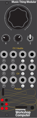 RandomnessTransposeClock RateUnusedUnusedPitchRandomnessClockTriggerVoiceAssignableAssignableAssignableAssignableAssignable
Controls
Randomness
Noon = random, fully CW = locked, fully CCW = locked and inverting (repeats at twice the loop length). Main, X and Y pick up (soft takeover) after the editor sets their value
Transpose
0 to +24 semitones
Clock Rate
Internal clock, about 1 to 16 steps per second
Lock / Layout: No bits flip; every loop repeats. Main chooses one of six layout slots saved on the card
Run: Main knob sets how often bits flip
Scramble: Randomise every bit inside a loop
Inputs & Outputs
Inputs
Outputs
Inputs
Unused
Not used
Unused
Not used
Pitch
1V/oct transpose, quantised to semitones
Randomness
Added to the Main knob
Clock
External clock. When unplugged the Y knob sets an internal clock
Trigger
Fires both envelopes
Outputs
Voice
The synth voice
Assignable
Chosen in the editor - an envelope, LFO, oscillator pitch or register lane (default filter envelope)
Assignable
Chosen in the editor (default Osc 1 pitch, calibrated 1V/oct, MIDI note 60 = 0 V)
Assignable
Chosen in the editor (default volume envelope), calibrated
Assignable
Chosen in the editor - envelope trigger (default), clock, register gate or register trigger
Assignable
Chosen in the editor - clock (default), envelope trigger, register gate or register trigger
LEDs
Register
Bits 0-3 of the register
Clock
Flashes on each clock step
Volume
Brightness follows the volume envelope; blinks fast while a knob is waiting to pick up a value set in the editor
README
Turing's Palette
An experiment for a larger card: a simple synth voice where every parameter is read from a Turing-Machine-style shift register.
The register is 64 bits long. In the web editor you split it into 1–8 loops (one 64-bit loop, four 16-bit loops, 20 + 12 + 16 + 16, anything that adds up to 64 or less). Each loop rotates on its own clock divider, and each has a chaos amount that scales how often the Main knob flips its bits. Then you drag each of the synth synthesis parameters onto any window of 1–16 bits and give it an output range. Windows may overlap, and may straddle two loops.
Quick start
- Insert the card and press reset. It starts with a four-loop layout, so it plays straight away.
- Patch Audio Out 1 to a mixer or speaker.
- Turn Y to set the clock speed, or patch a clock into Pulse In 1.
- Main at noon gives an ever-changing pattern. Turn Main fully clockwise, or push the switch up, to lock the loops.
- Open the web editor in Chrome or Edge, connect with a USB-C data cable, and start dragging parameters around.
The voice
Two oscillators (morphing sine → triangle → saw → square) → mix → resonant 12 dB low-pass (state-variable, run at 96 kHz) → VCA. Osc 2 can frequency-modulate Osc 1 (through-zero FM), with its own envelope on the FM depth, and Osc 2 can be soft- or hard-synced to Osc 1. Five attack/decay envelopes, all fired together: filter, volume, FM depth, and a pitch envelope for each oscillator. All but the FM one have a curve control.
| # | Parameter | Range | Notes |
|---|---|---|---|
| 0 | Env Trigger | 0–1023 | Fires both envelopes when ≥ 512. Checked only on clock steps where its own bits moved. Unassigned, it fires every step if Min ≥ 512. |
| 1 | Osc 1 Pitch | 0–48 scale degrees | Quantised to the editor's scale, counted up from the root note |
| 2 | Osc 2 Pitch | −24…+24 scale degrees | Relative to Osc 1, same scale |
| 3 | Slew | 0–1023 | Glide, off to about 1 s |
| 4 | Osc 1 Shape | 0–1023 | sine → tri → saw → square |
| 5 | Osc 2 Shape | 0–1023 | sine → tri → saw → square |
| 6 | Osc Mix | 0–1023 | Osc 1 → Osc 2 |
| 7 | Cutoff | 0–1023 | 20 Hz – 14.5 kHz, exponential |
| 8 | Resonance | 0–1023 | Self-oscillates near the top |
| 9 | Cutoff Env Amt | −1023…+1023 | Bipolar |
| 10–12 | Filter Attack / Decay / Shape | 0–1023 | 1 ms – 4 s; shape: slow start ↔ linear ↔ snappy |
| 13–15 | Vol Attack / Decay / Shape | 0–1023 | as above |
| 16 | FM On | 0–1 | Osc 2 modulates Osc 1's frequency when 1. The depth glides in and out over ~3 ms, so switching doesn't click |
| 17 | FM Offset | 0–1023 | Base FM index 0–4 (256 = index 1). Linear through-zero FM: above index 1 Osc 1's frequency swings through zero and its phase runs backwards, so the pitch stays centred at any depth. Osc 2's pitch and shape set the ratio and colour |
| 18 | FM Env Amt | −1023…+1023 | How far the FM envelope moves the index from the offset (256 = index 1 at the peak); negative dips it. The total stays within index 0–4 |
| 19–20 | FM Attack / Decay | 0–1023 | 1 ms – 4 s, fixed snappy curve |
| 21 | Osc 1 P.Env Amt | −1023…+1023 | Osc 1 pitch envelope depth, ±48 semitones (256 = an octave), smooth rather than quantised; it starts from and returns to the scale note |
| 22–24 | Osc 1 P.Env Attack / Decay / Shape | 0–1023 | 1 ms – 4 s; shape: slow start ↔ linear ↔ snappy |
| 25–28 | Osc 2 P.Env Amt / Attack / Decay / Shape | as Osc 1 | With FM on, sweeping Osc 2 sweeps the FM ratio |
| 29 | Sync | 0–2 | 0 off, 1 soft, 2 hard. Osc 2 follows Osc 1: each time Osc 1 starts a cycle (either way round, with through-zero FM), hard sync restarts Osc 2's cycle, so it plays at Osc 1's pitch with Osc 2's pitch setting the brightness; soft sync reverses Osc 2's direction instead, a gentler version. Sweep Osc 2's pitch or pitch envelope for the classic sync sound |
| 30–33 | Pitch LFO Rate / Shape / Sync / Depth | 0–1023, Sync 0–1 | Vibrato on both oscillators, depth up to ±12 semitones |
| 34–37 | Vol LFO Rate / Shape / Sync / Depth | as above | Tremolo: the LFO's lower half pulls the level down, by up to all of it |
| 38–41 | Filter LFO Rate / Shape / Sync / Depth | Depth −1023…+1023 | Moves the cutoff either way, in cutoff units |
| 42–44 | Audio Out 2, CV Out 1, CV Out 2 | −1023…+1023 (−5…+5 V) | Output lanes, see Outputs below |
| 45–46 | Pulse Out 1, Pulse Out 2 | 0–1 | Output lanes, see Outputs below |
LFOs
Three LFOs, each with Rate, Shape, Sync and Depth lanes. Rate runs from about 0.02 Hz to 50 Hz; with Sync on it chooses a length in clock steps instead (1/4, 1/2, 1, 2, 3, 4, 6, 8, 12, 16, 32 or 64 steps per cycle, from the measured clock, internal or Pulse In 1) and the LFO restarts on the right step. Shape morphs sine → triangle → saw → square, and its top tenth is random: a new level held for each cycle (sample and hold). Depth 0 (the default) leaves the sound untouched.
Outputs
Audio Out 2, CV Out 1, CV Out 2 and both pulse outs each have a lane, and a Sends choice on its Parameter card:
| Output | Can send | Default |
|---|---|---|
| Audio Out 2, CV Out 1, CV Out 2 | its register value raw (−1023…+1023 = −5…+5 V) or quantised to the scale (1 V/oct); Osc 1 or Osc 2 pitch (1 V/oct, MIDI note 60 = 0 V); the filter, volume, FM or either pitch envelope (0…+5 V); the pitch, volume or filter LFO (±5 V) | Filter env, Osc 1 pitch, volume env |
| Pulse Out 1, Pulse Out 2 | a register gate (high while the lane reads 1), a register trigger (5 ms on each step where it reads 1, if its bits moved), the envelope trigger, the clock | Envelope trigger, clock |
The CV outs are calibrated; Audio Out 2 is not (about ±6 V across its range). An output's lane only matters while it sends its register; otherwise its bar greys out.
How bits become values
For each assigned parameter, the bits start … start+width−1 are read with start as the
least significant bit, either
- Binary: as a binary number, normalised to 0…1, or
- Count: the number of set bits divided by the width (smoother, more "probabilistic" movement),
optionally inverted (1 − x), then scaled to Min + x × (Max − Min). Setting Min above
Max also reverses the direction. An unassigned parameter is fixed at its Min value.
A held parameter keeps the value it had when you held it: the register goes on stepping, but that parameter no longer follows it. Hold is saved with the layout. When a slot loads, a held parameter takes the value the slot's saved register pattern gives, and holds that. A held Env Trigger acts like a fixed setting: held at "fire" it fires on every clock step, held at "rest" never.
How the loops move
On each clock step, every loop whose divider is due shifts its bits up by one place.
The bit falling off the top of the loop goes back in at the bottom, and is flipped with
probability p × chaos. p comes from the Main knob (plus CV In 2), as on the Turing Machine:
| Main | p | Result |
|---|---|---|
| fully CW (or switch up) | 0 | locked loop |
| noon | 0.5 | random |
| fully CCW | 1 | locked, inverting every pass, so it repeats at twice the loop length |
Bits outside every loop never move. Assignments can still read them, as fixed values.
Panel
| Control | Function |
|---|---|
| Main | Randomness (see above) |
| X | Transpose 0 to +24 semitones |
| Y | Internal clock, about 1–16 steps/s (used when Pulse In 1 is unplugged) |
| Switch up | Lock; Main chooses the layout slot (see below) |
| Switch middle | Run |
| Switch down | Scramble every bit inside a loop |
| Pulse In 1 | Clock |
| Pulse In 2 | Fire the envelopes |
| CV In 1 | 1V/oct pitch, semitone quantised |
| CV In 2 | Added to Main |
| Audio Out 1 | Voice |
| Audio Out 2 | Its output lane (default: filter envelope) |
| CV Out 1 | Its output lane (default: Osc 1 pitch, calibrated 1V/oct, MIDI note 60 = 0 V) |
| CV Out 2 | Its output lane (default: volume envelope), calibrated |
| Pulse Out 1 | Its output lane (default: envelope trigger) |
| Pulse Out 2 | Its output lane (default: clock) |
| LEDs 0–3 | Register bits 0–3 |
| LED 4 | Clock |
| LED 5 | Volume envelope; blinks fast while a knob is waiting to pick up |
| LEDs 0–5 | For 1.5 s after a layout is chosen: the LED of its slot (blinking if the slot is empty) |
Layout slots
The card keeps six layouts in flash, one per LED. Each slot holds a layout, the register pattern it was saved with, and a name (up to 16 characters).
- On the module: with the switch up the loops are locked, so Main is free to choose a slot. Its travel is split into six zones, slot 1 fully anticlockwise to slot 6 fully clockwise. Flicking the switch up only shows the playing slot on the LEDs; a layout loads once you turn Main into another slot's zone, and its LED lights for 1.5 s. An empty slot's LED blinks and nothing loads. Back in the middle, Main does nothing until it reaches its randomness setting again (pick-up), so the loops don't suddenly unlock at a different setting.
- At power-up the card plays the slot it last played. (It notes the slot in flash once it has stayed chosen for 5 s, so sweeping Main doesn't wear the flash.)
- In the editor, the Layouts on the card panel lists the six slots when the card connects, with their names and loop layouts and the one playing, and follows any change made with Main. Save here saves what is playing into a slot under the name typed above the list; Load, Rename and Clear (two clicks) do the rest. Save to card in the header saves into the slot that is playing.
- Firmware before 0.6 kept one layout; the first time 0.6 or later starts, that layout becomes slot 1, "Saved". A fresh card starts with the factory layout in slot 1.
- New firmware keeps your slots: each layout format only adds parameters at the end, so the card reads layouts saved by earlier firmware, and the parameters they lack take their factory settings (Sync off, for example).
Web editor
web/index.html is a single static page, styled and connected the same way as the CVSeq and
WaveSeq editors. It works without a card: it simulates the register so you can design layouts
and watch the parameter values move. With a card connected over USB (WebMIDI SysEx, Chrome/Edge
on desktop or Android; not iOS) the card is the source of truth: the page reads the card's
layout when it connects, then shows the card's register, knobs and switch about 30 times a second.
- Knobs & clock shows Main, X and Y as the card is using them, and the switch position. Move a slider to set that value on the card: the module's knob then picks up (soft takeover). It does nothing until it is turned to, or past, the new value, so nothing jumps. While a knob is waiting, its box has a dotted outline, an orange line shows where the knob is, and LED 5 on the module blinks fast.
- The dashed box above the grid (the tray) holds any unassigned parameters, as small chips: drag one onto the grid to give it bits, or drag a bar into the tray to unassign it. Drag a bar to move it, or its ends to resize it. Drag on an empty lane to draw a range.
- Lanes come in groups: Notes, Oscillators, FM, Filter, Volume, Pitch envelopes, LFOs and Outputs. Click a group's name to fold it to one row (its bars stay visible, in miniature), or use Fold all / Unfold all. The editor remembers which groups are folded.
- The pause button, beside each parameter's name, holds it at its current value; its bar greys out. Click again to let the register move it. The parameter panel has the same Hold button.
- Click a parameter's name to select it. The Parameter card beside the grid shows its own bits live, in the grid's order with their bit numbers, what they read as (the binary number, or how many are set in Count mode) and the value that gives. It stays in view while you scroll down the grid: it and the cards below it form one column that stays beside the grid as the page scrolls, and scrolls on its own (mouse wheel over it) when it's taller than the window. Below the bits are its range, mode, Invert, Hold, and where it sits.
- Drag the handles on the loop strip to move loop boundaries. The Loops table sets length, clock divider and chaos per loop, and can split, merge or remove loops.
- Click a state bit to flip it (on the card too, when connected).
- Every edit goes to a connected card straight away. Save to card stores the layout and the current register pattern in the slot that is playing, so they come back after power-off; the Layouts on the card panel saves into, loads, renames and clears any of the six slots.
- Layouts can be exported and imported as JSON.
SysEx protocol
Documented in full in sysex.h. Every message is F0 7D 50 <cmd> … F7
(50 is 'P'); the card shows up as a MIDI device named Turing's Palette.
| Cmd | Direction | Data |
|---|---|---|
01 HELLO |
editor → card | card replies with STATE and SLOTS |
02 STATE |
card → editor | protocol version, layout (405 bytes as nibbles), Main/X/Y settings, each parameter's value in use (14-bit, offset by 8192) |
03 SET_CONFIG |
editor → card | protocol version, layout (405 bytes as nibbles) |
04 SAVE |
editor → card | slot, name (16 bytes): save the playing layout and register into a slot and play from it; card replies SAVED (08, slot) and SLOTS |
05 SET_REG |
editor → card | the register, 8 bytes little endian, as nibbles |
06 RESET |
editor → card | factory layout; card replies with STATE |
07 STATUS |
card → editor | ~30/s while pings arrive: register, step and trigger counters, switch / external clock / knob-waiting flags, Main/X/Y settings, physical knob positions, flip probability, the two notes, the playing slot and which slots hold layouts |
09 PING |
editor → card | every second; keeps STATUS flowing |
0A KNOB |
editor → card | knob (0 Main, 1 X, 2 Y), value 0–4095 as two 7-bit bytes; the knob then picks up |
0B LOAD_SLOT |
editor → card | slot: play it; card replies STATE and SLOTS |
0C CLEAR_SLOT |
editor → card | slot: empty it; card replies SLOTS |
0D GET_SLOTS |
editor → card | card replies SLOTS |
0E SLOTS |
card → editor | count, playing slot, then per slot: used, number of loops, 8 loop lengths, name (16) |
0F RENAME_SLOT |
editor → card | slot, name (16) |
Layout byte layout (CONFIG_FORMAT 6): [0] format, [1] number of loops,
[2..25] 8 × (length, divider, chaos), [26..27] scale mask (bit n = n semitones above root),
[28] root MIDI note, [29..404] 47 × (enabled, start, width, flags, min lo, min hi, max lo, max hi)
with flags bit 0 = count mode, bit 1 = invert, bit 2 = hold, bits 3–7 = source (output lanes), and min/max as signed 16-bit little endian.
Building
mkdir build && cd build
cmake .. -DPICO_SDK_PATH=/path/to/pico-sdk
make
Builds against Pico SDK 2.1.1.
ProcessSample must finish inside ~20 µs (about 3000 cycles at 144 MHz) on every sample, or
the Computer's knob and CV readings get mixed up. So no sample does a burst of work: after a
clock step the loops shift one per sample and the parameters are re-read one per sample; a
layout from the editor is prepared on the USB core and swapped in by pointer; pitch, smoothing,
pitch envelopes, LFOs, outputs, knobs, LEDs and the editor snapshot each run on their own staggered
samples. Measured in an
emulated Cortex-M (QEMU, instruction counts, hardware divider modelled) the worst sample is
about 1,650 instructions and the average about 1,150, with FM at full depth, hard sync,
both pitch envelopes, all three LFOs and quantised outputs running. It has not yet
been timed on hardware;
if you change the audio path, check it with a scope on a spare GPIO.
Credits
Firmware and editor written with AI assistance (Claude). The USB/SysEx link, knob pick-up and editor style follow the CVSeq and WaveSeq cards. MIT licence.